Table of Contents
 This page in German (Seite auf Deutsch)
Please order via email: mail@webtemp.org
Frequently asked questions
Installation
What else do I need? Which power supply can I use?
CoolTWILED needs to be supplied with 24 volts DC. We have made good experiences with Meanwell power supplies.
To calculate the minimum needed power, please add all wattages of all connected LEDs, then add a margin of about 10%.
Which fans do I need? Are more or less than two fans possible?
For LED cooling, two standard 12 volt, 3pin fans (which normally are used as pc case fans) are needed.
CoolTWILED's two fan ports are connected in series. Please use two identical fans.
CoolTWILED 3.x SLAVE is available without or with fan ports. These behave exactly like the ports of the master board.
Unfortunately, there are fan models that cannot be connected in series (for example the flat fans made by Scythe). In general, the most simple models work best. Please do not use fans with built-in temperature sensors.
It is also possible to operate four identical fans in parallel (via two Y cables, one per port). The current is then twice as high as compared to one fan per port.
If CoolTWILED is supplied with 12 volts, you can use a single fan. Due to the series connection of the two ports you have to bridge the other one (e.g. use the jumper).
Please do not exceed a fan current of 1 A and do not use a single 12 volts fan when using a 24 volts power supply.
Why different output currents? Can't I just dim?
Dimming does not have the same effect as setting a lower current has: Dimming is achieved through PWM.
Example: Output A is configured to 1000 mA. If you dim down to 50%, this means that in reality the output is alternating quickly between 1000 mA and 0 mA. So even if the average current is 500 mA, it is not recommended to connect a 700 mA LED to this output. It might age faster.
Multiple masters
Each master board acts as a separate network device and thus can be programmed individually. Different hostnames should be used (please see tab “Wireless”).
Do not interconnect multiple masters via their link ports!
Random generators of all master boards run synchronously to generate clouds and thunderstorms at the same time everywhere (within the accuracy limits of the resonator).
Is it possible to change the output currents?
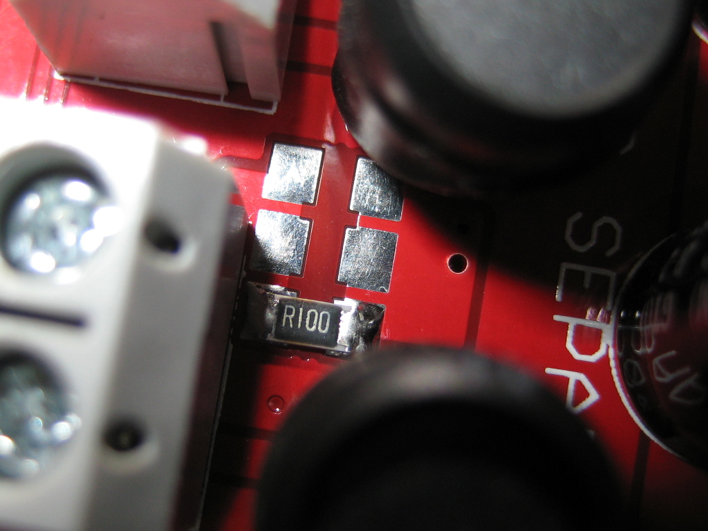
Yes, but it is difficult due to the narrow space between the connectors and the coils, where the relevant resistors for each output are located (top side of the board). Common combinations of resistors and the resulting currents are listed on the bottom side of the board. The SMD pads are connected in parallel and each resistor adds a certain current (or in general I = 100 mV / R):
R100 (0.1 Ohm):  1000 mA
R150 (0.15 Ohm):  667 mA
R200 (0.2 Ohm):   500 mA
R220 (0.22 Ohm):  455 mA
R300 (0.3 Ohm):   333 mA
R330 (0.33 Ohm):  303 mA
R470 (0.47 Ohm):  213 mA
R620 (0.62 Ohm):  161 mA
1R00 (1 Ohm):     100 mA
These are the resistors used by us. We can mail you some if needed.
We can also change the currents for you. The price is 5 EUR per output plus 20 EUR for cleaning and testing plus shipping.
Drilling jigs
Jigs for the mounting holes (suitable for M3 screws) can be found here: Drilling jigs
Soldering
When handling electronics please take precautions to avoid electrostatic discharge (ESD). Wear cotton clothing and avoid shoes with rubber or plastic soles. Unless necessary, touch the circuit board only in non-metallic locations like the edges.
Equipment: Please use a temperature controlled soldering iron. It is best to use a soldering station and set it to a maximum of 360 degrees Celsius (680 degrees Fahrenheit). We recommend wide soldering tips with a chisel shape (because of better heat conduction). Solder wire with flux cores and a thickness of 0.5 mm.
Observe the polarity of all the components but the coils. For the electrolytic capacitors, a + is printed on the circuit board at the corresponding position.
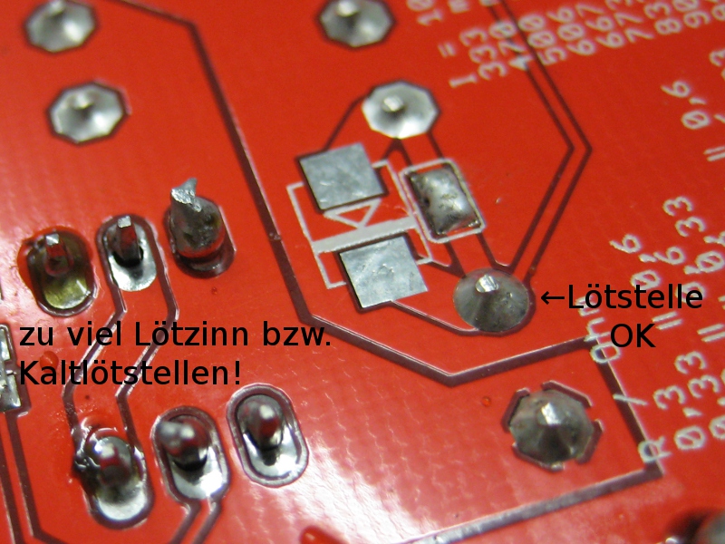
Please solder carefully since corrections are often difficult. Fully insert a component and make sure it is straight. While soldering, apply a little amount of solder first and only add more if necessary. Do not touch other components with the soldering tip.
Before powering on, make sure no loose tin residues can cause short circuits. Also take care of bare cables, the display or temperature sensor.
Please do not attempt to clean the solder joints using solvents since this can easily create short circuits.
LEDs
How many LEDs can I connect?
CoolTWILED offers 12 outputs, all of which can be controlled separately. Via software a label can be selected for each channel from a predetermined list (e.g., “White” for channel A).
0, 1 or 2 (in series) 10W LEDs for fish tanks can be connected per output, so with one CoolTWILED you can operate at maximum:
24pcs 10W white/blue
or
18pcs 10W white/blue and 2pcs 10W/20W RGB
or
12pcs 10W white/blue and 4pcs 10W/20W RGB
It is very important to wire all outputs separately. No part of a LED string may come in contact with a part of another LED string (or housing, ground, etc.).
The above LED counts apply if the board is supplied with 24 V. The voltage only determines the maximum number of LEDs per output. Otherwise, it is irrelevant, since LEDs are operated with constant current. LED drivers on each output keep the currents constant at the set value. Therefore, you can also connect a single LED. The efficiency will then drop by only about 5%. Despite the overall high efficiency, a few watts of heat are generated, especially when running at the limit. The coils generate some heat and also do the LED drivers on the bottom. CoolTWILED contains several mechanisms to prevent overheating. In general, however, it is recommended to guide the airflow of the LED fans so that the top of the PCB receives some of it. This is mandatory when output currents equal to or above 1000 mA are involved. Any number of outputs can also be left open.
Do not connect anything else but LEDs to the outputs. No fans or similar things! For this purpose there are two fan ports on the board.
If you need more LED power, one or more CoolTWILED 3.x SLAVE can be connected.
I have my own LEDs. How many can I connect?
If you have little knowledge of electronics, it is recommended to use the LEDs for fish tanks offered on this site. These are individually tested, the technical data (currents and voltages) are known, there is support and suitable connection plans exist.
We cannot make any statements or recommendations regarding third-party LEDs. You'll have to rely on your data sheets.
In general, the following rules are to be observed:
- Know the maximum currents of your LEDs and do not connect them to outputs which supply higher currents. The LED drivers of each output will keep the current at the configured value. So, along with your order, send us a list of the currents you need. For your reference, we'll put the current configuration on the second page of the invoice.
- No part of a LED string may come in contact with a part of another LED string (or housing, ground, etc.). Make sure the anodes and cathodes of your LEDs are electrically insulated from the cooling surface (measure it).
- The voltage at the outputs is always smaller than the (power supply) voltage at the input of the board. Therefore, if the board is supplied with 24 volts, 0 to 6 (in series) single LED chips can be connected per output. This means in total 12 * 6 = 72 LEDs can be connected. If fewer LEDs are connected, the output voltage is automatically matched.
- If your power supply offers slightly more than 24 volts, you might be able to connect 7 LEDs in series. If you do that, it is important to verify the actual current does not exceed 1500 mA. Regular Meanwell power supplies have a potentiometer that can be used to increase the voltage to about 27 volts. Remember that CoolTWILED's maximum input voltage is 30 volts and you need some safety margin (do not use a 30 volts power supply).
LED stripes / LEDs with a common cathode or anode
LED stripes or other (RGB) LEDs with a common cathode may NOT be connected to CoolTWILED.
A common anode overrides the current control, so that these LEDs only work in exceptional cases: If the LEDs have series resistors and the power supply voltage is equal to the rated voltage of the LEDs (this is often the case with stripes) it may work. But there is no guarantee for this.
LED stripes with individual connections for each color (cathode and anode) are in use by various customers.
However, we do not recommend LEDs stripes, since they offer inferior brightness, energy efficiency, price/performance and lifetime when compared to high-power LEDs.
LEDs with 30 or 50 watts (or more)
CoolTWILED 3.x can supply a maximum of 1500 mA per output. If you connect LEDs which need more, these LEDs will work, but they won't reach their rated brightness.
The maximum input voltage of CoolTWILED is 30 volts. Since a certain safety margin is needed, do not use a 30 volts power supply. LEDs which need more, won't work at all.
This means that ideally two LEDs with 10 watts each should be connected in series per output. We offer these LEDs for fish tanks as well.
How to connect the RGB LEDs?
The three colors of the RGB LEDs are to be connected separately. This is important, since the outputs of the board must not come in contact with each other. Two RGB LEDs require three outputs with 350 mA (for 10W RGB LEDs) or 700 mA (for 20W RGB LEDs).
Example for the default configuration:
- Port G+ → Red LED1 → Red LED2 → Port G-
- Port H+ → Red LED3 → Red LED4 → Port H-
- Port I+ → Green LED1 → Green LED2 → Port I-
- Port J+ → Green LED3 → Green LED4 → Port J-
- Port K+ → Blue LED1 → Blue LED2 → Port K-
- Port L+ → Blue LED3 → Blue LED4 → Port L-
Please see also the connection diagram further up on this page. In case of a customized current configuration, the connections must be made according to the set currents (see page two of the invoice)!
What efficiency can I expect?
The following measurements were taken with one or two (in series) white 10W LEDs and a 24 V power supply unit using a slave board (unlike when using a master board, this permits exact measurements since there is no own consumption). The board was installed in a housing and was actively cooled along with the mounting plate on which the LEDs were mounted. The setup was left running for some time before measurement, until all values remained stable.
Single LED
- Input voltage: 23.96 Volt
- Input current: 398 mA
- LED voltage: 9.64 Volt
- LED current: 933 mA
- Efficiency: 94.3 %
Two LEDs in series
- Input voltage: 23.8 Volt
- Input current: 778 mA
- LED voltage: 19.37 Volt
- LED current: 930 mA
- Efficiency: 97.3 %
Software related questions
Are firmware updates free of charge?
Yes. CoolTWILED is shipped with its microcontroller and WLAN module already programmed. We offer regular updates when new features are implemented and bugs are fixed: Software manual.
Does the power supply have to run all the time?
CoolTWILED includes a buffered real-time clock. Thus, time is running even during a power failure. Once switched back on, the light schedule automatically continues at the correct line. Additionally, the clock is set once an internet connection is established (if available).
In order to save the standby current of the power supply you can also use an external timer and switch off your power supply at night. CoolTWILED can also be left running 24/7 if continuous temperature measurement with CoolTWITemp 1.x (temperature sensor) or a moon phase simulation/night light is desired.
Troubleshooting
WLAN connection problems
The red LED on the WLAN module (b/g/n 2,4 GHz) signals the presence of supply voltage.
Please make sure that the device is switched on and located in the reception area. Problems related to reception quality / shielding are best dealt with by creating ventilation slots or a cutout in the housing next to the BT module. This is also helpful if you plan to use the IR remote control option. It is also possible your power supply is interfering. Many power supplies are potential-free. In these cases connect GND to PE.
If WLAN settings have been entered before, these can be deleted manually.
PWM noise
Dimming by PWM can in some cases produce a quiet buzzing sound. It should not be troublesome. If the case resonates, re-mount the board using plastic washers.
If the supply lines are too thin (the cables from the power supply to the circuit board), this can also affect this kind of noise negatively (due to the high resistance the supply voltage drops periodically). Please use at least 1.5 mm² and ensure a good fit.
Coils and/or electrolytic capacitors which have not been soldered properly can be a cause, too. All components also have to be fully inserted and straightened before soldering.
In some cases, the coin cell may touch the coil of output G and transmit vibrations. Try pulling out the coin cell by one millimeter.
The PWM frequency can be changed on the tab “Expert options”. Change the value next to “PWM prescaler”. The higher the value, the lower the frequency. The default value is 12, which results in approx. 470 Hz. For the new value to stay active after the next cold start, save the settings to EEPROM.
Prescaler 3 results in 1.5 kHz
Prescaler 10 results in 555 Hz
Prescaler 20 results in 291 Hz
Prescaler 50 results in 120 Hz
Prescaler 100 results in 60 Hz (not recommended since this causes visible flickering)
Troubleshooting the fans
Most of the problems associated with fans are caused by the fact that they do not work when connected in series, as it is the case on CoolTWILED (see also below “Which fans do I need?”).
For the following two tests, switch off the power supply and disconnect the fans:
Quick test using a multimeter in diode test mode
Negative multimeter electrode (black) to board input +
Positive multimeter electrode (red) to fan port - (the port next to the coil)
You should see 0.1 to 0.3 volts.
Positive multimeter electrode (red) to board input -
Negative multimeter electrode (black) to fan port - (the port next to the coil)
You should see 0.7 to 1 volt.
Testing the transistor (FMMT619)
Positive multimeter electrode (red) at B (base of the transistor, pin 3)
Negative multimeter electrode (black) at C (collector, pin 2) or E (emitter, pin 1)
In either case, you should see 0.5 to 1 volt.
If your multimeter lacks a diode test function, you can measure the resistance instead. There must not be a short circuit (<1 Ohm).
The PWM signal for the fan control is connected to the base (pin 3) of the transistor via a resistor.
Of course, we thoroughly test the fan control function of each board before shipping.

Output X does not do what it is supposed to do (for example, it is always off or on)
If you can rule out an operating error or a software problem (please test in manual mode and check the white balance settings), the following tests can help with further diagnosis (switch off the power supply first):
(1) There are two fuses next to the input connector, which can be tested easily with a multimeter. Resistance should be close to 0.
(2) Quick test of the LED drivers (the chips with 6 pins on the bottom- next to each output): Disconnect all LEDs, switch multimeter into diode test mode, put the positive multimeter electrode to board input - and the negative multimeter electrode to - of an output. Values of approximately 0.5-0.6 volts are ok (the output stage of the driver is ok).
(3) Next measurement: Negative multimeter electrode to board input + and positive multimeter electrode to - of an output. Values of approximately 0.1-0.3 volts are ok (the diode is ok). Both values are temperature-dependent (the warmer, the smaller).
(4) The resistors for the current setting can be roughly tested by measuring the resistance between the board input + and the respective + of an output. It should be less than 1 Ohm. Resistors damaged by short circuit will have higher values.
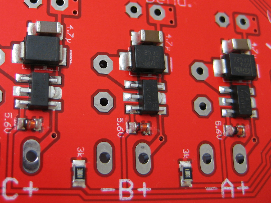
(5) When running, it is possible to carefully check whether the PWM signal is correctly applied to the LED driver. There is a 3k resistor next to each chip, at the edge of the board. At 100%, you should measure 5 volts across the resistor and 0 volts at 0%.
Hint for all measurements: Compare the values of different outputs to each other and look for deviations.
The open circuit voltage of outputs has no meaning at all.
Of course, each output of each board is thoroughly tested for correct function and correct current before shipping.
LED drivers are sensitive and damage can be caused by e.g. overheating, ESD (electrostatic discharge), short circuits, wiring errors, board bending, or moisture. If you cannot solder SMD, we will help you with a repair including cleaning and test and usually do not charge more than 50 EUR plus shipping: mail@webtemp.org.
Repairs are only possible if no conductive traces or solder pads are damaged (e.g. thermally or by corrosion). Please do not send us fans, power supplies or other case parts without asking beforehand. Important: Please ship electronics in an ESD shielding bag! Note that we do not send replacement boards without trying to repair first.
Error codes (flashing letters) in the display
A built-in self-diagnosis can find some errors automatically. These are then indicated by letters flashing in the display. Additionally, hints are displayed on the “Channels” tab.
!
“Overtemperature”: Once a temperature of 60 degrees Celsius is reached on one of the sensors, CoolTWILED dims to a very low brightness to avoid damage. Normal operation is resumed after all temperatures have fallen below 40 degrees Celsius. To analyze cooling problems, you can monitor the temperatures over time (tab “Charts”).
V
“Undervoltage”: If the input voltage is below 9 volts, no operation is possible. This can also be caused by a defective fuse at the board input.
Q
“Quartz error”: The oscillator crystal of the real-time clock does not work. Please measure the coin cell voltage (should be about 3 volts). Check whether the time is set correctly and whether the time is still correct when the power supply was switched off for some time.
X
“Checksum error”: The firmware in the flash memory of the microcontroller is faulty. A firmware update should fix the problem.
The following errors are all associated to bus communication and occur when the data transmission does not work, i.e. the corresponding component does not respond:
T
Communication problems with the onboard temperature sensor. In addition, the error “Overtemperature” will appear and all channels dim to a very low brightness.
C
Communication problems with the real-time clock. Possibly a short circuit of the coin cell (to case/ground). Disconnect circuit board, remove the error, restart.
P
Communication problems with the PWM controller. If this is the case, LED brightness cannot be controlled.
Severe problems with the bus system often result in several fault codes being displayed at once.
Checklist:
- What happens after a reboot?
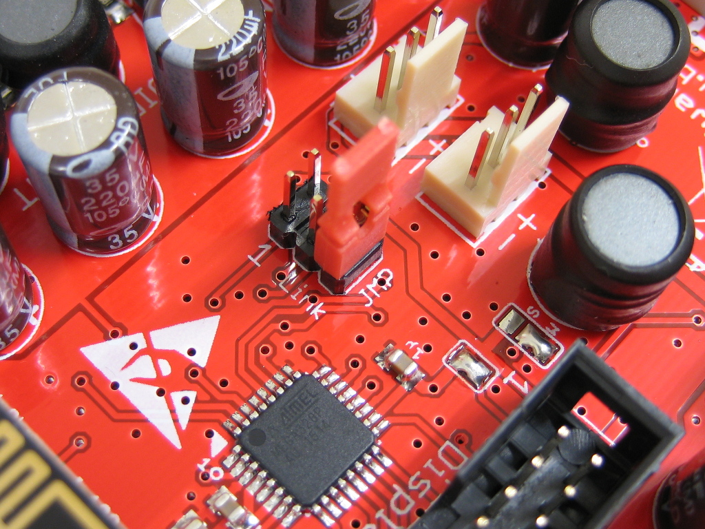
- Is something connected to the link port? If present, remove the jumper! Is CoolTWITemp (temperature sensor) connected correctly? Pin 1 of the connector is highlighted by a little arrow. What happens if the link port remains open?
- Other possible causes include short circuits to ground at the link port itself. Switch off the power supply and use a multimeter. The data pins are the two in the middle (3 and 4). There should be no low-resistance connection between them and between them and ground.
- If the measured values are ok, a firmware update should be attempted. This also restores all settings to their default values.
If the display remains dark
If a firmware update was attempted and it failed, the process can be repeated. To do this, the bootloader must be forced at start-up: Switch off the power supply and at the Link port, plug the jumper into position JMP. Do not put the jumper into positions other than the described one. If the power is turned back on, the display backlight should be flashing (with no text) for a few seconds. After that the booting should succeed and the jumper needs to be removed. Please note that all settings (including the WLAN) settings will be reset.
If the display remains dark and you suspect the hardware to be defective, narrowing down the problem is only possible with a precise error description. Is the supply voltage present at the board input connector (use a multimeter)? If so, please power off and check the two fuses at the board input (bottom). The fuses must be low-resistance (<1 Ohm). If the fuses are ok, you should be able to measure 5 volts between pins 1 and 2 on the display (or the display connector) during operation. If this voltage is present and the board is also found by the software, follow the steps described in the first paragraph (re-flash the firmware).
LEDs are flashing after a few minutes / cooling the board
The flashing is a safety feature of the LED drivers. On the inside chips are much warmer than on the outside. The drivers switch off at a chip temperature of 160 °C and do not resume until they have cooled down to 140 °C. These temperatures can damage semiconductors. If the coils get hot, their magnetic properties degrade and thus cause even greater losses. Our advice is to cool the board in a way so that all parts still can be touched without burning your finger at all times.
Even though the efficiency is very high, the board should be cooled actively when LED currents equal to or above 1000 mA are involved. At 1500 mA, the drivers are at their limit and active cooling is mandatory. You should mount CoolTWILED on the same metal plate (top), on which the LEDs are mounted (bottom). The air flow generated by the fans is sufficient for cooling.
Rule of thumb: For electronics, always assume that a difference of 10 degrees Celsius approx. double or half its lifespan.
If the LEDs are already flashing a few seconds after power-on, the wiring is faulty and must be corrected immediately! All outputs must be wired separately. Each output must be connected to the correct LED string individually and the strings must not come in contact with each other or ground/case at any point (not even through the heat sink). This can not be measured when connected, you have to track all the cables.
 02:37:50 up 324 days, 20:40, 0 users, load average: 9.06, 9.45, 9.69